GLDRR
Guided Landing Drogue for Rocket Recovery (GLDRR) is a system to autonomously navigate payloads to desired locations.
Technologies: PCB, electronics, sensors, controls, rocketry
Overview
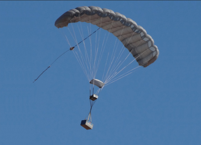
Figure 1: Similar system - GPHAR II
The objective of GLDRR is to design, build, and test a system that can autonomously guide a rocket from apogee down to predetermined GPS coordinates before deploying a larger main parachute to bring the rocket’s descent rate down to safe levels.
Traditional rocket recovery methods (single, dual deployment, and GPS systems) are insufficient as rockets reach higher altitudes and are prone to a myriad of problems that complicate recovery operations.
GLDRR seeks to alleviate these problems.
The current design developed over the course of this semester consists of a parafoil, two winch servos, a microcontroller, GPS sensor, and LiPo batteries mounted on a 3D printed electronics sled which is housed in a commonly used coupler/avionics bay form factor.
The microcontroller will take input from the GPS sensor and use the winch servos to guide and control the heading of the rocket throughout its descent.
I worked on a team with two other students and my roles were to design/build the electronics, software, and portions of the control algorithm.
Overall Design
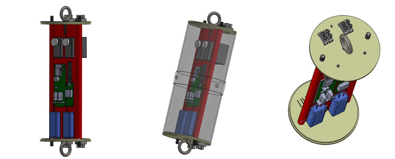
Figure 2: Avionics Bay CAD - Multiple Views
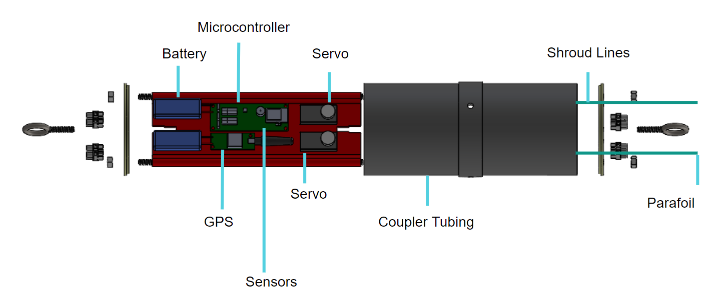
Figure 3: Avionics Bay CAD - Exploded View
Electronics Design
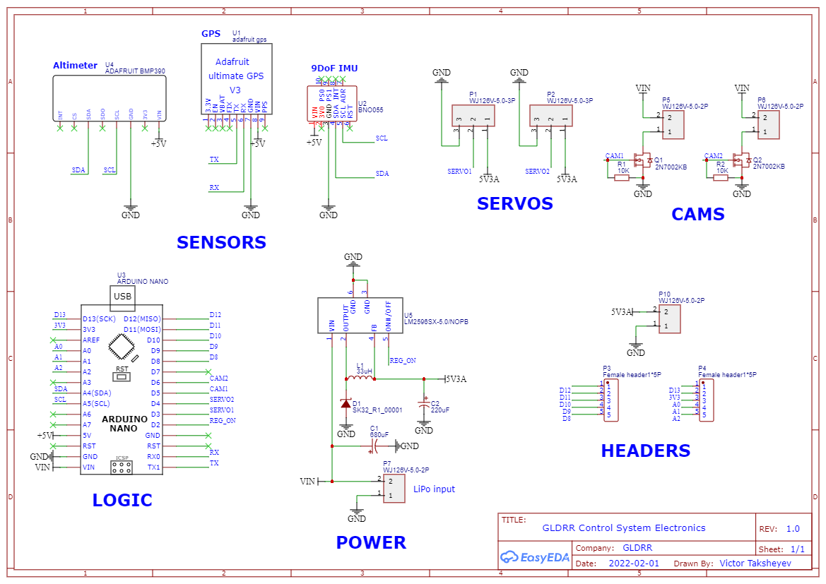
Figure 3: GLDRR Electronics Overview
GLDRR's control algorithm relies on an accelerometer, GPS, and altimeter. These sensors feed data into the microcontroller over the I2C interface. The microcontroller uses the sensor inputs for a control algorithm. Following a computation cycle, it outputs a command to the two servos attached to the parafoil shrouds. There are also cameras which will record the flight for post-processing. The microcontroller, sensors, servos, and camera require different voltages. Therefore, the last part of the electrical system is a power distribution sub-circuit to provide the necessary voltages.
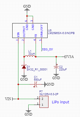
Figure 4: GLDRR Electronics Overview
The microcontroller has an embedded voltage regulator; however, a voltage regulator was needed for the servos which operate between 4-6V. To do this, the 2S LiPo input would be passed through the LM2596 step-dowm voltage regulator to produce a steady 5V power supply.
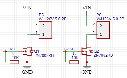
Figure 5: Camera Circuit
In order to conserve onboard memory and power, the team would like to start the cameras autonomously when the rocket lifts off. This can be detected using the accelerometer and a signal could be sent from the microcontroller once such an event occurs. As a result, the two onboard cameras are connected to MOSFET transistors which will be able to supply appropriate power (from the LiPO) once a launch event is detected.
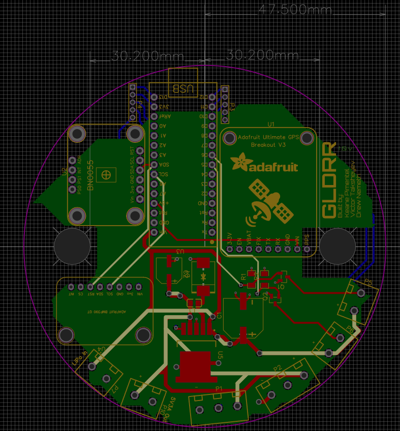
Figure 6: PCB Design
A circular PCB was chosen to maximize the area. The PCB will be sledded into the avionics bay shown in Figure 2.
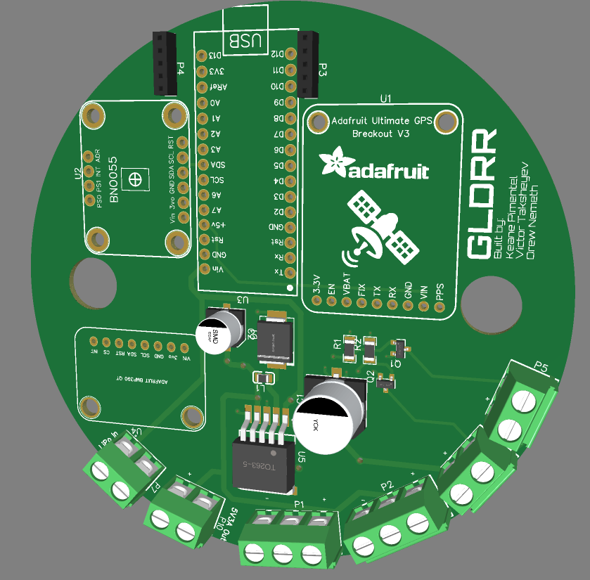
Figure 7: 3D View of PCB
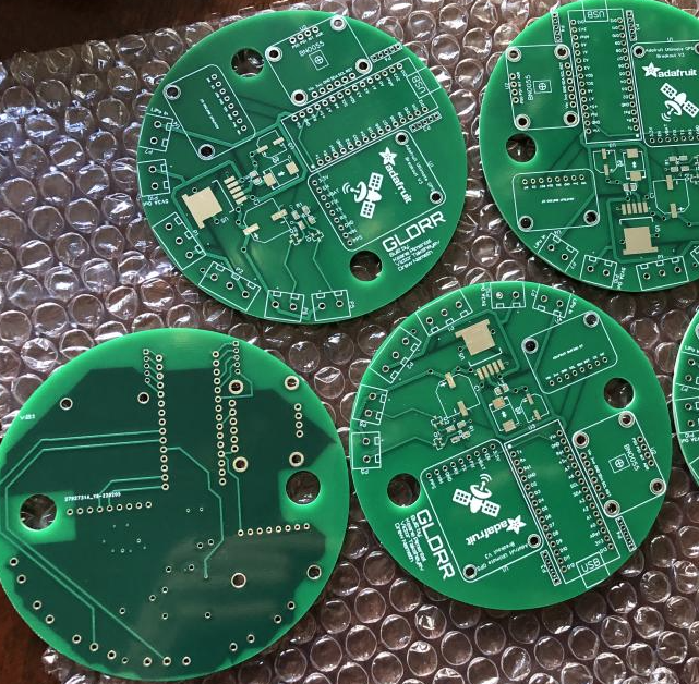
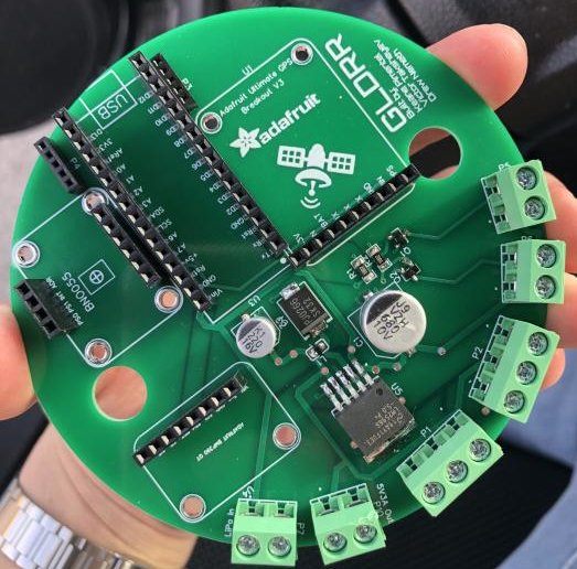
Figure 8: PCBs before and after soldering
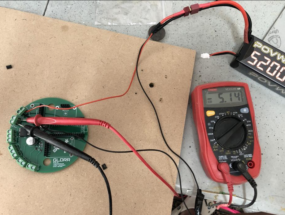
Figure 9: Testing Voltage Regulator Circuit
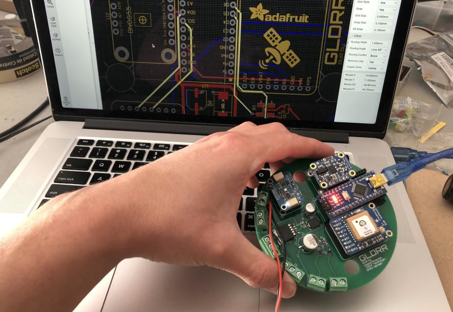
Figure 10: Fully Integrated Test
Most recently a fully integrated test of all PCB electronics was performed and all were operating properly. Data was read from all sensors using the I2C interface, the transistor switches were able to be enabled, and the servo controller was working properly.
Next Steps
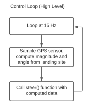
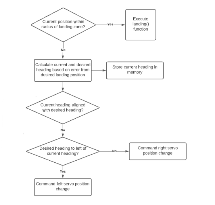
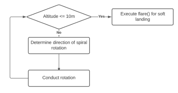
Figure 11: High Level Control Algorithm
Following the implementation of the control algorithm, testing will be done on a drone (simulating a rocket flight) and then a fully integrated test on a rocket.
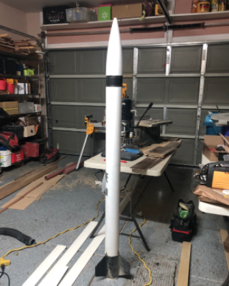
Figure 10: Rocket That Will Launch GLDRR
victortaksheyev@gmail.com