MARTy
Martial Arts Robotic Trainer (MARTy) is a robotic sparring partner that fights back!
Technologies: CAD, 3D Printing, Electronics, computer vision, Raspberry Pi, woodworking
Overview
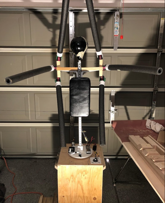
Figure 1: Front view of the robot
MARTy was a fun personal project I thought of to make over winter break. It taught me a lot about CAD, robotics, and interdisciplinary engineering. The robot is able to punch from 6 different angles and rotate along its base to track a sparring partner's motion and always appear in front of them while they're sparring.
Software
There are two primary pieces of software on this project:
- Object (facial) tracking
- Hardware controllers
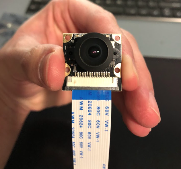

Figure 2: Facial Tracking Using Camera
The face detection algorithm identifies the largest visible face and determines the center of it. It then computes a position error between the center
of the face and the center of the image. This error is fed to the motor controller which spins the motor in the correct location until the error is eliminated.
Currently, only proportional control is used with a large acceptable margin, but upgrading to a PD controller will allow for quicker error response.
A further upgrade to a PID controller will eliminate the need for an acceptable margin as it could eliminate steady state error.
The face detection is based on a pre-trained Haar cascade classifier on frontal faces. I added optimizations to make it run faster on the Raspberry PI.
Figure 3: Face Detection Computing Error From Center
Figure 4: Initial Motor Control Testing
Following an arming and calibrating sequence, the motor was controlled by sending a PWM signal to the electronic speed controller (ESC). Furthermore, motor direction was controlled using a reverse function of the ESC. Once the object detection error changed signs, reverse was toggled. The motor was able to be reversed while running (which acted as a brake). This significantly simplified the reverse logic.
Addressing Servo Jitter

Figure 5: Servo Jitter - GIF source: Ben Akrin Blog
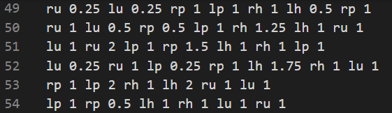
Figure 6: Punch Combo Definitions
To make it easy to add and change MARTy's actions, the combos it can perform are pre-defined in a text file that is parsed and read by the program.
Each line represents a combo. the number following the punch acoronym represents the delay before the next punch.
For example, ru 0.25 lp 1 rh 2 defines a combo sequence consisting of a right uppercut followed by a left punch after 0.25 seconds, followed by a right hook after 1 second.
Mechanical
Figure 7: MARTy CAD
The robot consists of a perforated metal pole as its base (spine). Onto that base, a combination of wooden and 3D-printed PLA elements were attached. The robot's shoulders are wooden for ease of prototyping. They are fixed to the metal pole with L-brackets. Servos for the arms are screwed into the wooden shoulders. The head is attached using a 3D-printed spring attachement. Finally, the pole is attached to a 3D-printed bearing plate that sits on a metal bearing. This allows the robot to spin and track its sparring partner. The bearing plate is designed as a large gear. A motor is connected to the gear using a belt pulley.
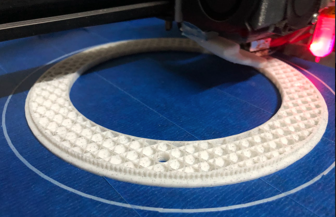
Figure 8: Bearing Plate Being Printed
The pulley being used to connect the motor to the bearing is a GT2 specification. To ensure the gear would work with the pulley, it was modeled using the following GT2 guide:
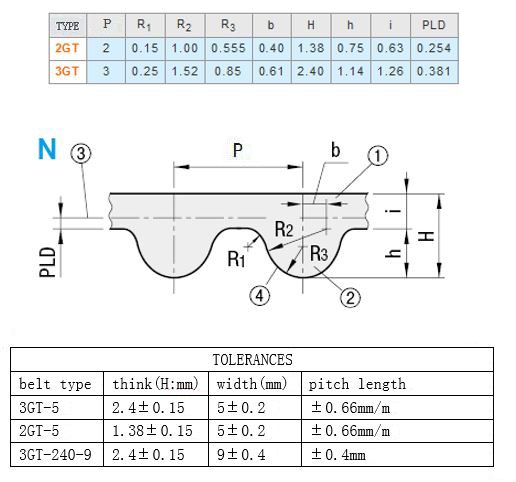
Figure 9: GT2 Pulley Specification
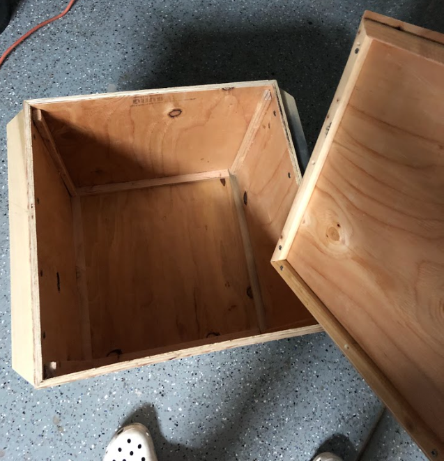
Figure 10: Base Box
My dad works with wood and helped me make the wooden base box to hold the robot and its supporting weights
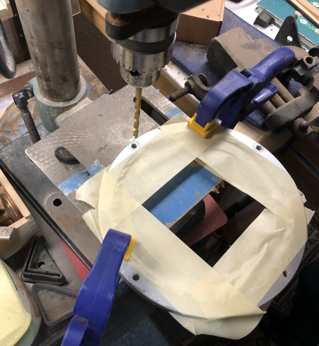
Figure 11: Drilling Holes to Attach to Wooden Base Plate
Figure 12: Bearing on Base Plate
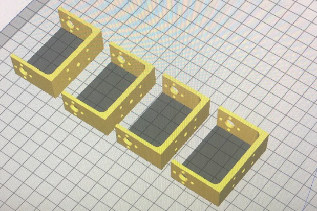
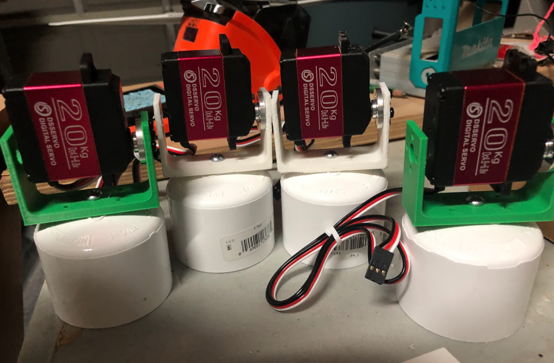
Figure 13: 3D printed servo connectors
Electronics
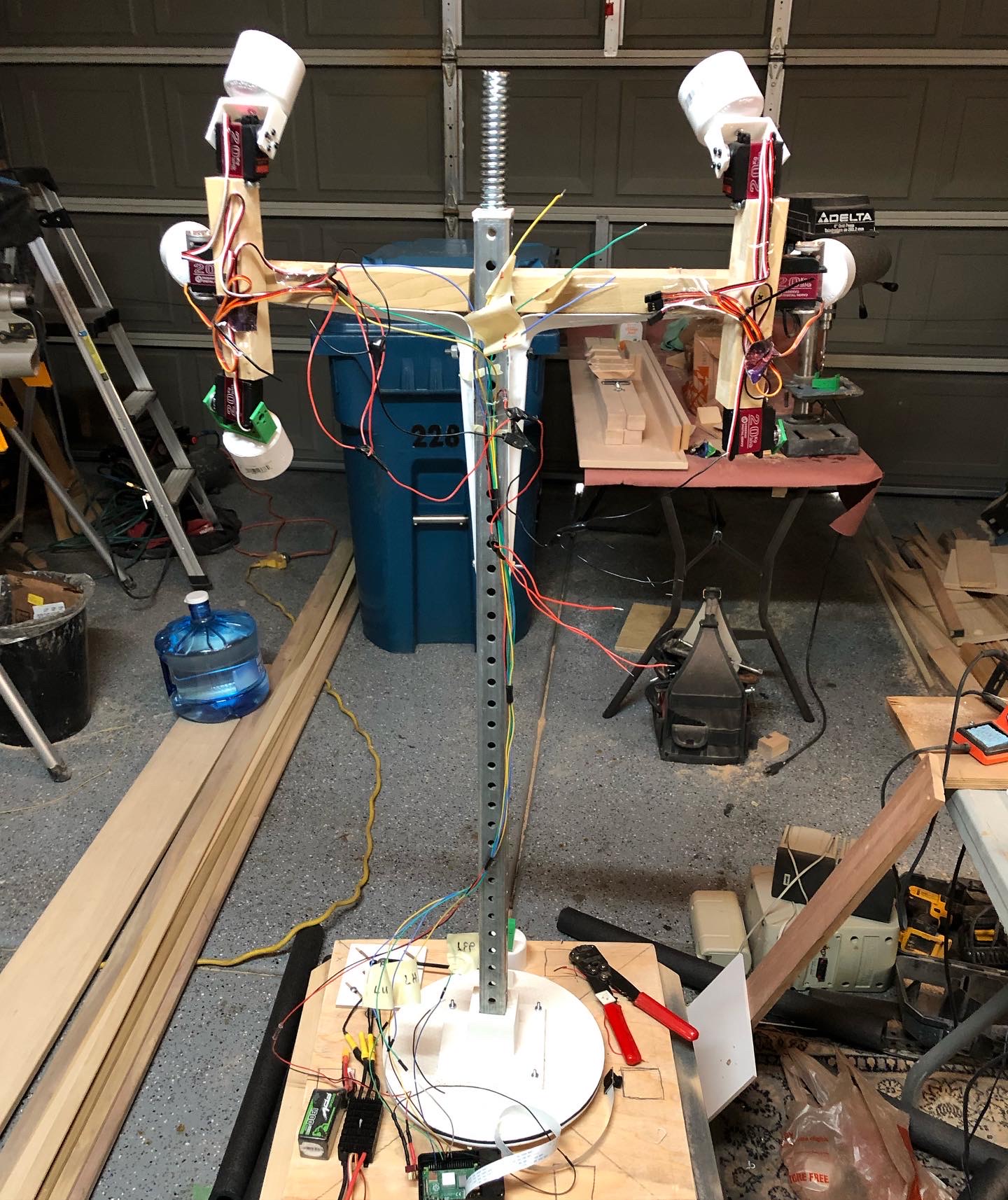
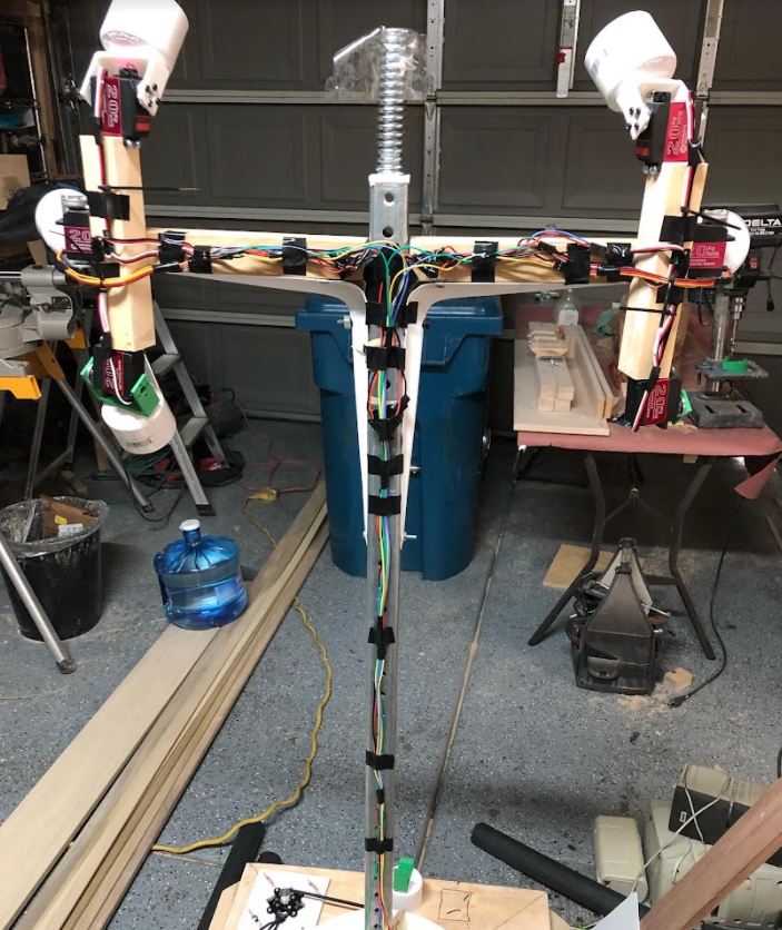
Figure 14: Wiring before and after cleanup
At max current draw, each servo is able to perform a punch in 0.16s.
Figure 15: MARTy punch test
Future Plans
In the future, I want to create an app where MARTy's settings and combos could be adjusted. I also want to upgrade the motor used for the revolving base to a higher torque motor suited specifically for rotating heavy objects. Lastly, I would make the entire mechanical structure more robust (especially the bearing plate/gear) to handle more significant loads.
victortaksheyev@gmail.com