Reaction Wheel
Controlling a Rocket's Roll in Flight
Technologies: electronics, sensors, rocketry, controls
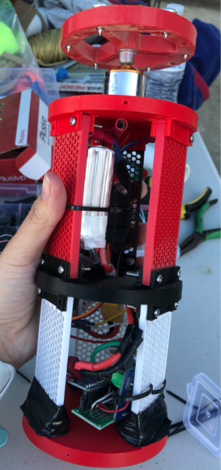
Final reaction wheel and electronics bay
The reaction wheel electronics contain 6 main elements:
- 3S LiPo Battery
- 6DoF IMU
- Microcontroller
- Electronic Speed Controller
- DC Motor
- External FRAM chip
The microcontroller samples roll data from the sensors at 60Hz. A rotational velocity error is computed that is then fed into a PID controller.
This controller determines the velocity and direction the motor must spin to create a counter torque that would null out the rocket's rotational velocity.
Following this computation, a signal is sent to the electronic speed controller to spin the motor.
Because the rocket would be flying at speeds exceeding mach 2 and was likely to encounter significant vibration and loads during flight, an FRAM chip was chosen for data storage
rather than an SD card. The limited capacity of the chip meant that logging should only start when the rocket begins flight. Because of this, the chip was enabled by the microcontroller once a launch event was detected using the accelerometer.
- Ki and Kd were set to small values
- Increased Kp until system oscillated
- Increased Kp until system oscillated
- Decreased Kp by half
- Increased Ki until SS offset is corrected
- Increased Kd until a loop is acceptably quick to reject disturbance
- $M_p = e^\frac{-\pi\zeta}{\sqrt{1-\zeta^2}}$
- $t_r \approx \frac{1.8}{w_n}$
- $t_s \approx \frac{4.6}{\gamma w_n}$
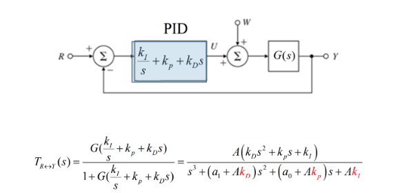
Second Order Plant with PID Parameterized for Kp, Ki, Kd Gains
After this theoretical calcualtion, there will likely still be an error because all aspects of the system (such as sensor noise) would not be perfectly modeled. Therefore, I would perform additional heuristic testing and tuning to achieve the desired response.
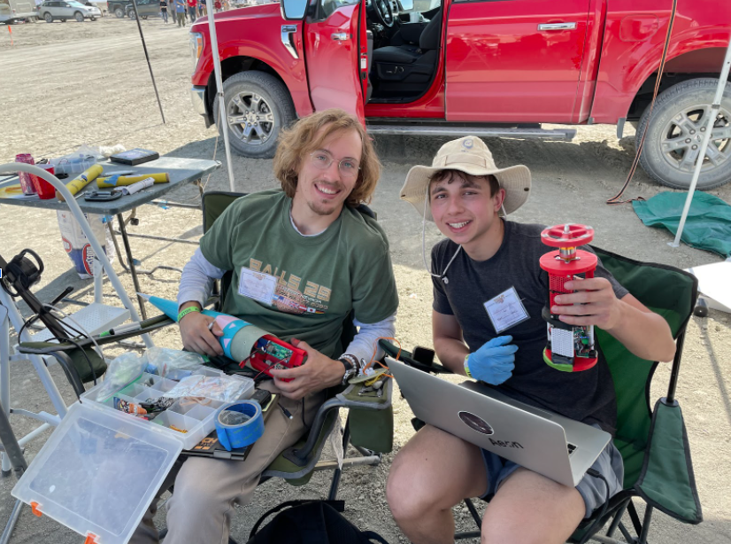
Final software update before payload integration with the rocket
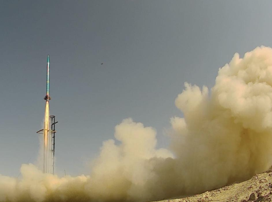
Rocket launch to 47k ft with Reaction Wheel Onboard
Previous generation electronics bay and wheel system, implemented in rocket and ready for a launch!
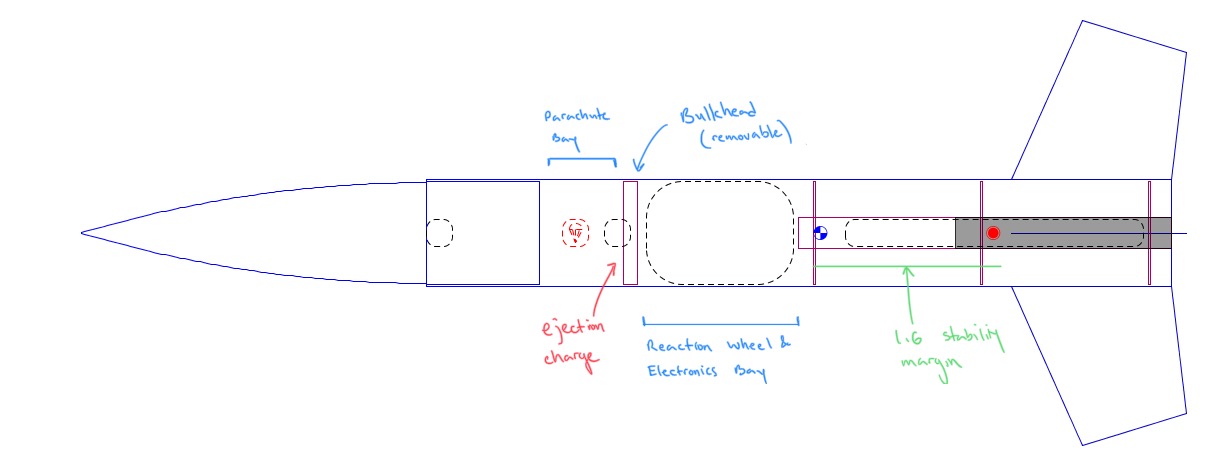
Rocket schematic, detailing placement of wheel
Initial Heuristic Testing
Position Loop PID Controller Testing
Velocity Control Testing
Following the Flight
During the flight, an anomaly occurred which caused the data logging to fail. It was determined to be a fault of accelerometer for detecting liftoff which enabled the rest of the system. An additional flight is planned in April of 2022 to test the system.
victortaksheyev@gmail.com